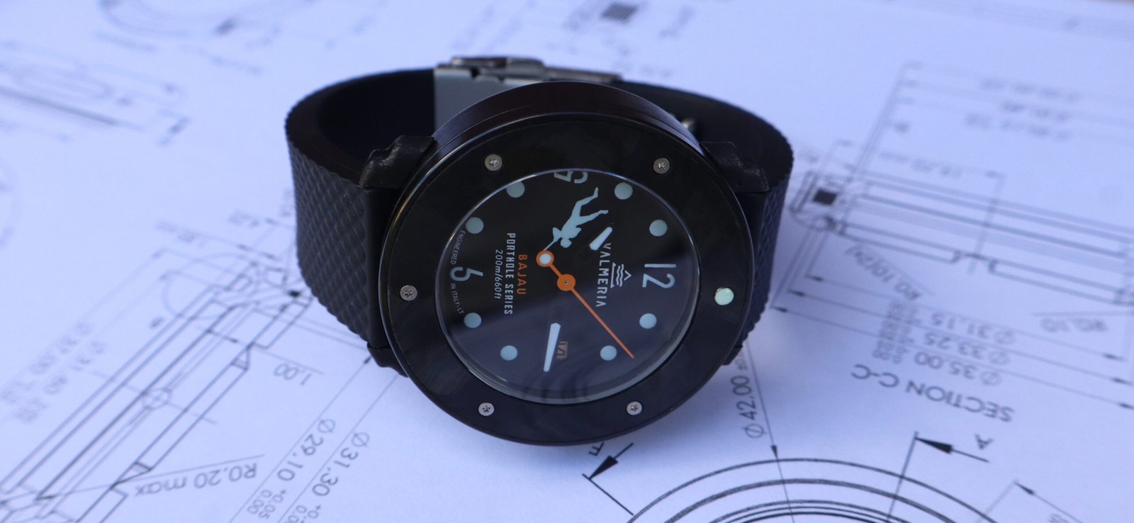
ENGINEERING & PROTOTYPING
behind the scenes of the porthole series
A watch inspired by marine exploration, featuring a patented design characterized by several nautical elements incorporated into the architecture of the case.
Two years of design, analysis and several prototype iterations preceded the final collection. As the first content of this section, we will briefly go through the four main ones.
Starting from a blank sheet, we designed every component of the watch in-house, without relying on standard components except for the movement. Through the different iterations, we were able to verify the geometries, functionality, materials and manufacturing processes, and ultimately the resistance of the finished product.
(Materials, geometries, manufacturing processes and performance were progressively refined until reaching the specifications of the finished product listed in the SHOP section).
1. a watch, not just a 3D-printed model
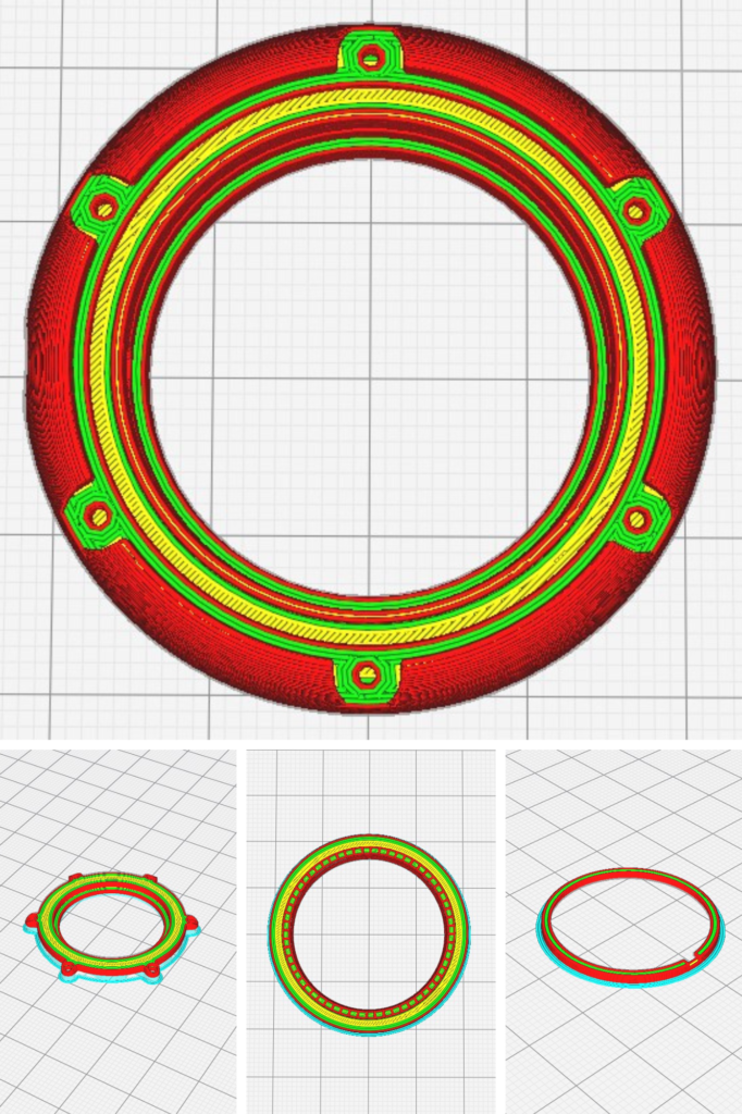
For the first prototype, we chose not to simply print a monolithic case model to check its proportions, as is typically done with 3D resin concepts. Instead, we individually printed all the main components of the case: the mid-case, caseback, bezel, movement spacer, and their respective assembly elements.
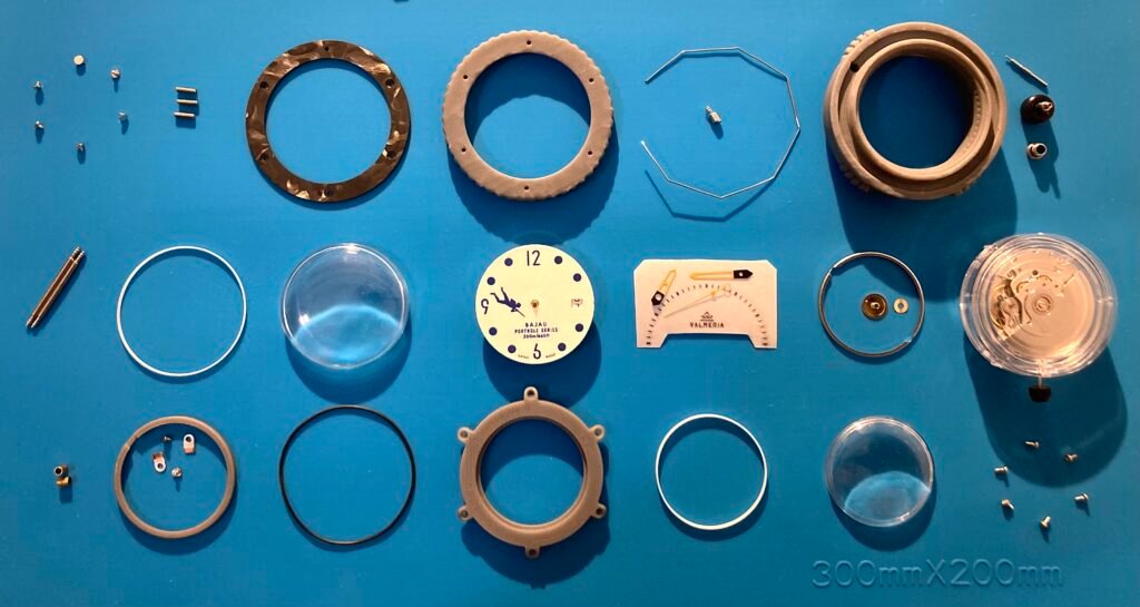
The objective, along with the fun of it, was to verify that the design was actually assembleable, functional, and “solid” even with such a material.
The prototype, though simplified, still included the crystals (plexiglass), gaskets, crown, bezel click system, and all the threads and micro-threads required for assembly.
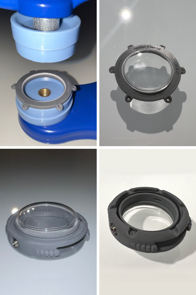
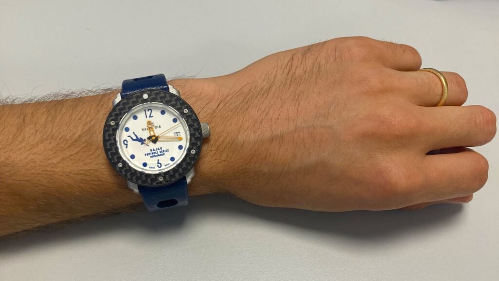
The most interesting part (after assembly) was the manual finishing required to achieve the proper mechanical tolerances and the creation of the M1 micro-threads.On an M1×0.25 thread, the height of the external thread profile is around 0.15 mm—quite crazy on a material as brittle as resin.The result was a fully assembled, functional resin concept with a rotating bezel and water resistance:
2. turning the project into metal
The second iteration represents the first transition from resin to metal.
The bezel and caseback were produced in 316L stainless steel using wire-based 3D printing and subsequently CNC-machined, bead-blasted, and anodized, while the mid-case was CNC-milled from a solid block of ERGAL, bead-blasted, and anodized.
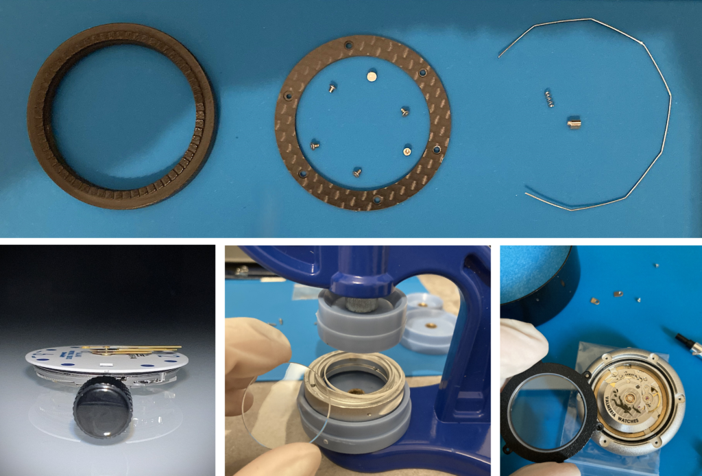
The wire-printed material consists of metallic powder bound by a polymer. After printing, the binder is removed, and the component is sintered at high temperature.
During sintering, the part shrinks: the 3D model is therefore oversized to compensate for the shrinkage expected from the process, typically in the range of 15–20%.
This test allowed us to see the design in metal for the first time, and to compare the finish and dimensional behavior between FDM, SLM, and CNC.
3. CONSOLIDATED GEOMETRIES
With the geometries now defined, we moved to laser powder bed fusion (LPBF), specifically SLM using an AlSi10Mg alloy.
Compared to FDM, the laser here selectively melts thin layers of powder, building the component layer by layer. An interesting aspect of this process is the extremely high cooling rate, which leads to the formation of a very fine grain microstructure. This fine grain structure enhances the material's mechanical properties (particularly its hardness and strength) well beyond what can be achieved from the same alloy using conventional manufacturing processes. It offers a lightweight alternative that comes remarkably close to the typical hardness values of steel, at just one-third of the weight.
Consequently, compared to the second iteration, the bezel and caseback transitioned from wire-based printing to powder-bed printing in AlSi10Mg. The mid-case, meanwhile, remained CNC-milled from a solid block of ERGAL, or aluminum bronze for the BrAl version.
We intentionally left extra material (a machining allowance) on the functional surfaces, subsequently finishing the components on a lathe.
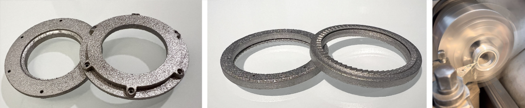
Gasket seats, centering diameters, and mating surfaces were therefore brought to the required dimensions and finish through conventional machining and subsequently anodized. During this phase, we actually experimented with various combinations of materials and treatments, including an aluminum bronze (BrAl) case paired with a hard-anodized AlSi10Mg caseback, bezel, and lugs.
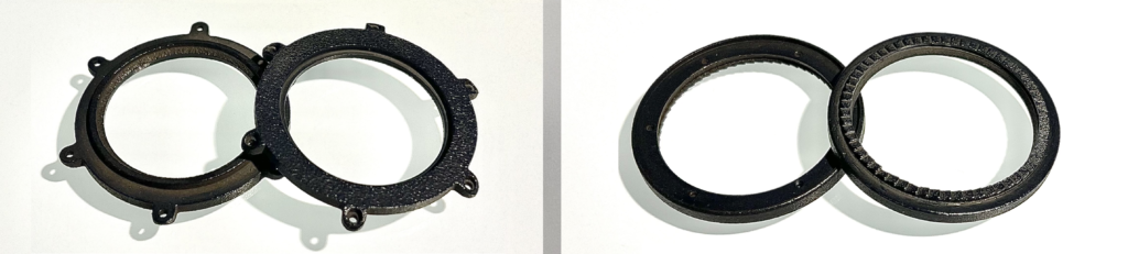
Hard anodizing, in addition to modifying the aesthetic appearance, electrochemically alters the surface of the material, creating an oxide layer that is significantly harder than the substrate and improving its resistance to wear and scratches.
For the bezel insert, during this phase we experimented with forged carbon—a composite material made of short carbon fibers in a resin matrix, compacted inside a mold.
We first built a disposable, 3D-printed PLA mold coated with silicone, consisting of a cavity, a punch, and an ejection system featuring a threaded pin and dowels positioned at 120°.
Next, we waxed the ejection ports to contain the material within the mold, and finally, the fiber and resin were weighed separately to control the reinforcement-to-matrix ratio before being brushed into the mold. In this case, it was not a critical parameter, as the primary goal was to familiarize ourselves with the process in anticipation of future projects involving components that will be subject to bending forces.
Following compaction, the component was demolded, trimmed, drilled, and hand-polished using diamond paste.
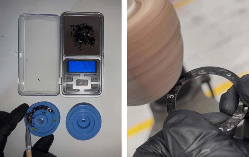
We could have obviously machined the insert from a carbon fiber sheet, but during this phase, we preferred to experiment and have some fun with the molding process.
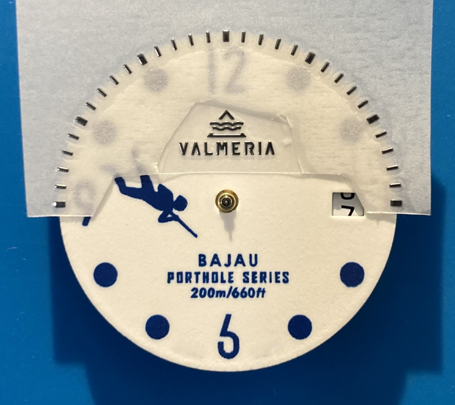
For the logo, we used electroforming:
a galvanic process starting with the logo design created using a photosensitive resin on a metal plate, which is then immersed in a nickel-based bath and subjected to direct current. This allows the metal to deposit layer by layer until a three-dimensional element is achieved.
The process makes it possible to reproduce even ultra-fine details with extreme precision, thanks to the material being deposited practically ion by ion.
At the end of the process, the logo is plated/colored, adhesive is applied, and it is covered with a transfer film for application onto the dial.
The hands are instead hand-lumed with Swiss Super-LumiNova® by RC Tritec.
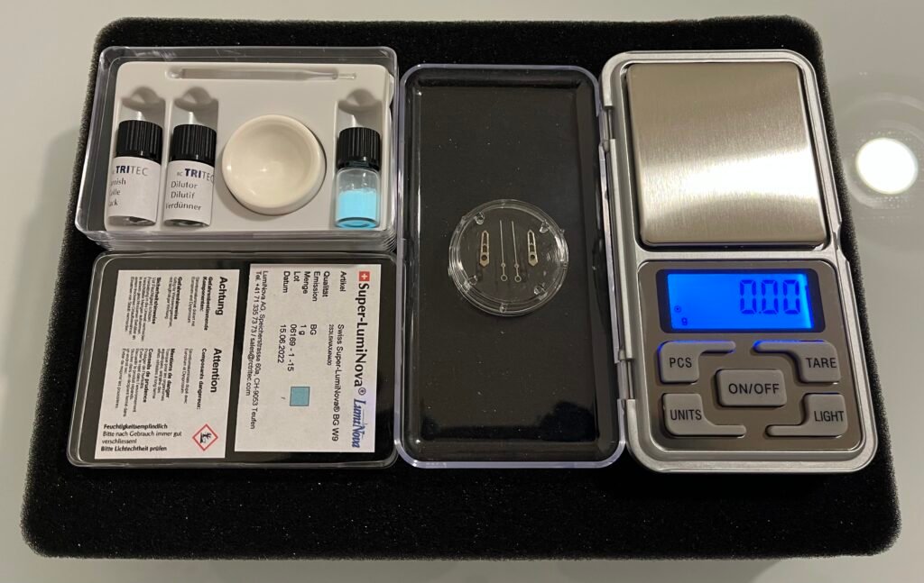
The compound is prepared by precisely dosing the powder, binder, and thinner: if the mixture is too viscous, it tends to distribute poorly and form clumps; if it is too fluid, it tends to run out.
A larger amount of pigment allows for a higher volume of luminescent material in the deposit, but it also alters the compound's viscosity, which is where the thinner comes into play to achieve the perfect balance.
The most delicate part occurs when the lume cavity has a fairly significant opening, as in this case, where the compound must remain suspended in the open space within the hand: for this reason, we first work on the contours of the cavity, creating a thin border of material to exploit the cohesion (surface tension) of the compound, which helps keep it suspended even in the central part:
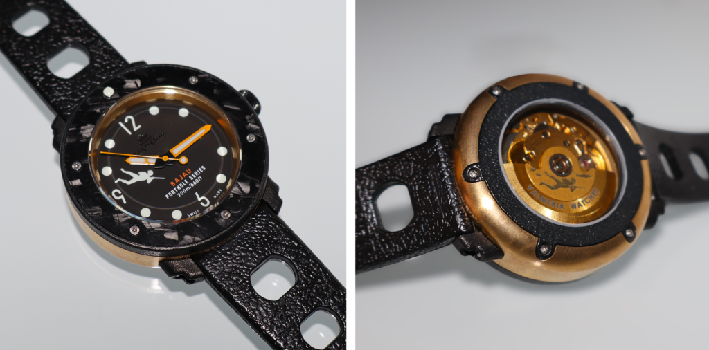
Assembly of the third iteration, BrAl version:
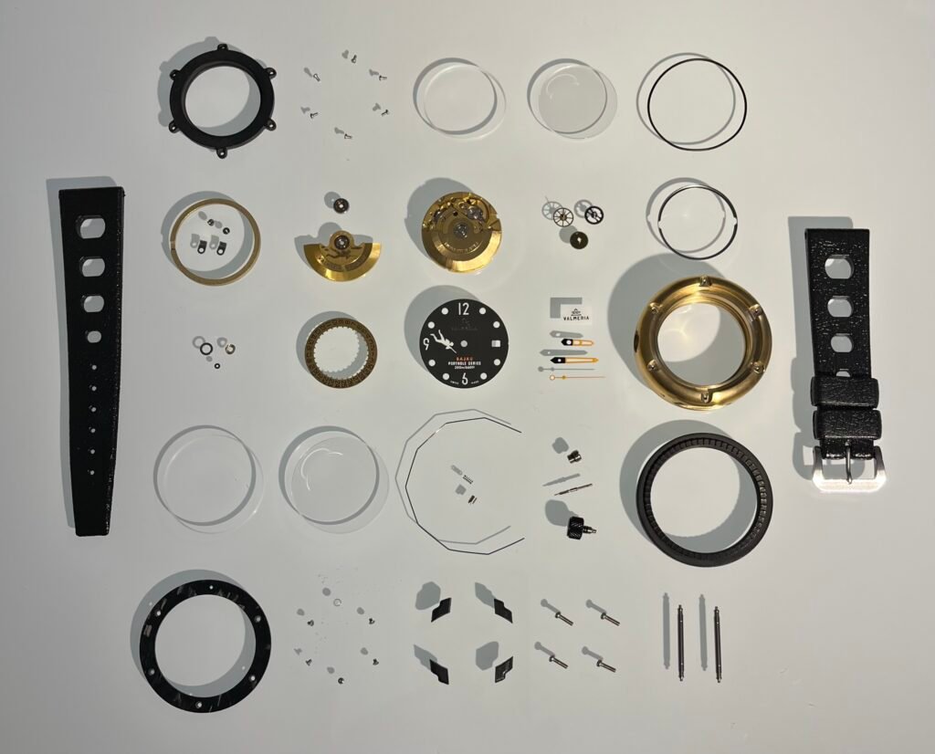
4. even more rugged
The final iteration consists of a small pre-series of 3 pieces, built with specifications very close to the definitive ones and dedicated to destructive testing.
The geometry is now virtually consolidated. The differences compared to the finished product mainly concern the movement and a few minor aesthetic and functional features.
For the tests, we used the Miyota 9015 instead of the Sellita SW200 planned for the final product.
The case, caseback, bezel, and crown are now CNC-machined from solid 316L stainless steel and subsequently coated in Titanium Aluminum Carbonitride (TiAlCN).
The lugs, however, remain printed in 316L via SLM and subsequently coated in TiAlCN due to their complex and unique geometry: we conceived them as minimalist elements, intentionally detached from the case to preserve its clean, circular, porthole-style profile.
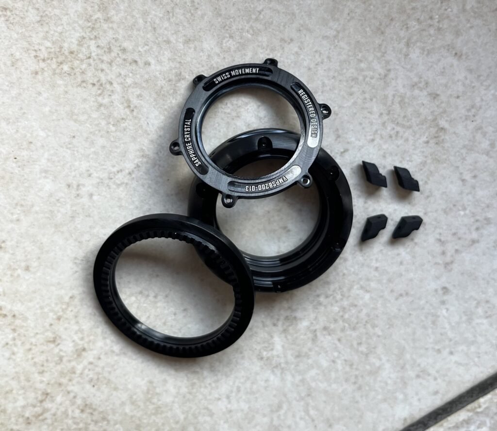
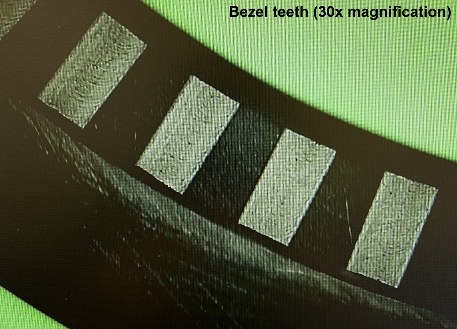
The bezel features teeth machined directly into the component using (for the first batch) sinker EDM.
EDM technology involves bringing an electrode close to the workpiece inside a dielectric fluid, where controlled electrical discharges between the electrode and the component locally melt and vaporize small amounts of material. The absence of cutting forces allows for ultra-fine geometries even on high-hardness materials, eliminating the mechanical deformations and burrs typical of chip-removal machining.
The result is a set of teeth characterized by sharper, more defined edges. In our case, this translates into a more precise engagement between the bezel teeth and the click system pin, ensuring a sharper, more controlled click over time, thanks to the increased wear resistance of the carbonitride-coated material.
The TiAlCN coating effectively forms a titanium-aluminum-carbon-and nitrogen-based ceramic layer that reaches surface hardness values in the range of 2,000 HV and beyond, far exceeding the most common PVD coatings.
Specifically, the addition of aluminum induces solid solution strengthening and self-passivating properties, while carbon reduces surface friction (> increased abrasion resistance).
An exceptional coating (originally developed for cutting tools), second only to diamond-like carbon (DLC).

This pre-series was created to undergo light diving, water-resistance testing, corrosion, impacts, and mechanical stress.
It is the final iteration before the definitive product, and its purpose is precisely to verify how the design performs when it stops being a prototype and is subjected to the actual operating conditions expected of a true tool watch.
From the first resin mockup, built almost at the absolute limit of what the material could withstand, to the 316L + TiAlCN pre-series, we have progressively increased robustness, water resistance, quality, and precision.